Duct penetration settings
In [project] > Specifications > Construction > Duct Penetration Settings, project administrators can add, modify, and delete settings for duct penetrations.
Penetration settings define for example which duct sizes can use these specific settings, how much empty space to have around the sides of the duct, and what materials to use in the penetration.
When a designer is inserting a duct penetration to a bulkhead or deck plate in the model, the designer can select which settings to use, as described in Penetration.
Defining duct penetration settings
Perform the following to define duct penetration settings.
Do the following:
-
In the Project Environment dialog, go to [project] > Specifications > Construction > Duct Penetration Settings.
-
Select New > Construction Settings.
-
You are prompted to select the penetration type. Select the required type, and then click OK.
- Flange using L-bars
- Flange using flat bars
- Flange using flat bars and doubler
-
Enter a name and description for the penetration settings object. Make sure that these provide enough information to the designers so that they can select appropriate settings for each penetration.
-
Create rules for the selected penetration type. For example, you might have one rule for duct sizes that use a small flange bar, and another rule for duct sizes that require a large flange bar.
-
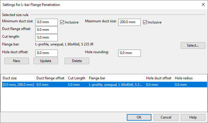
To add a rule, define the rule settings:
-
Minimum duct size, Maximum duct size – Specify the range of duct sizes that will use this rule. If Inclusive is selected, the rule applies also to ducts whose side length exactly matches the specified value.
-
Duct flange offset – Specify the distance from the outer side of the duct to the reinforcing flange around the opening.
-
Cut length – Specify a length that should be cut away from the duct piece inside the penetration, or zero to not cut the duct. This setting is only available for the type "Flange using L-bars", and the cut length is measured from the middle of the width of the L-bar, in the direction away from the angle where the legs of the L-bar meet.
-
Flange bar – Click Select to select the material to use for the flange bar.
-
Doubler bar – Click Select to select the material to use for the doubler bar. This setting is only available for the type "Flange using flat bars and doubler".
-
Hole duct offset – Specify the distance from the outer side of the duct to the side of the hole.
-
Hole rounding – Specify the radius for rounding the corners of the rectangular hole.
Then, click New. The new rule is added to the rule list.
-
-
To modify a rule, select the rule from the list, edit the settings, and then click Update.
-
To delete a rule, select the rule from the list, and then click Delete.
-
-
When all required rules are specified for this penetration type, click OK to close the penetration settings editor.